


Chapter 1
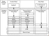
Overall protocol structure for RANAP
Iu-CS interface protocol
.Radio Access Network Application Part,(RANAP) is SS7 user layer. The Iu interface is specified at the boundary between the UMTS Terrestrial Radio Access Network (UTRAN) and the Core Network (CN). MSC is the functional entity used in the CS domain of the CN. It is connected to the UTRAN through the Iu-CS interface. Its interface runs RANAP protocol .
.Iu-CS interface protocol includes:
-Control Plane :It includes control plane signaling RANAP and Signaling Bearer
-User Plane:It includes User Plane protocol IuUP and Data Bearer
-Transport Network Control Plane:It includes data bearer control signaling ALCAP and Signaling Bearer

Overall protocol structure for RANAP
.The TS25.412 Specification provides two ATM based signaling bearer modes: Broadband SS7 (SAAL-NNI, MTP3-B, SCCP) and IP bearer SS7 (IP, SCTP, M3UA).
.From the point of view of layers, RANAP can be divided into two parts: radio access network Application Protocol in the Radio Network Layer, using RANAP protocol (TS25.413), and the Signaling Bearer, resident in the Transport Network Layer.

Chapter 2
RANAP main function and classification of message
2.1 RANAP Main Function
.RANAP protocol mainly complete the functions between CN and RNC following :
-Connection foundation, backout , Data transportation;
-ASN.1 coding/decoding and message checking;
-Overload Control;
-Paging;
-Reset and Reset Resource;
-Security Mode Control;
-Moving;
-Subscriber Resource Configuration;
.Besides the functions in front , RANAP modul add some correlated characteristic of production. It includes backup rearrangement, alarm ,calling statistic,testing,traceand so on .
2.2 RANAP message code/decode
RANAP message adopts ASN.1 PER code. Its massage need decoding tolls to analysis. The type of message is fixed in front two bytes of position in message code. The following code example is RANAP message Relocation Complete:
0x00 0x0D 0x40 0x03 0x00 0x00 0x00 0x00
Thereinto:The first byte 0x00 denotes procedure initiating message; The second byte 0x0D denotes process code,and 0x0D denotes Relocation Complete procedure;According to the front of two bytes,We can judge that the message is Relocation Complete message.
A RANAP message only with message type, its ASN.1 PER code is 7 bytes,which likes last example. the length of RANAP message can not less than 7bytes after ASN.1 PER coding.
2.3 Classification of RANAP message
.According to different message transport modes, RANAP EPs are classified into: connection-oriented and connectionless.
.The former is supported by a UE specific signaling connection for transport; the latter is supported by a common signaling connection for transport. All other procedures use connection-oriented service to transport except that Reset, Reset Resource, Overload Control, and Paging use SCCP connectionless service and Error Indication bases the actual conditions to make a determination between the connectionless service and the connection-oriented service.
.Connection-oriented messages are ones between a specific UE and the network, such as UE location update procedure and call procedure. Connectionless messages are ones pertaining to system maintenance and administration and affect part or all of UE users . Most of RANAP connectionless message may be up or down (except PAGING). Most of connection-oriented messages are unidirectional (except ERROR INDICATION and DIRECT TRANSFER).
Chapter 3
RANAP elementary procedures
3.1 Classification of RANAP Elementary Procedures
.According to different response types, RANAP EPs are divided into Classes 1, 2 and 3.
-CLASS 1:Elementary Procedures with response (success /or failure). For Class 1 EPs, “Successful” means a signaling message explicitly indicates that the elementary procedure successfully completed with the receipt of the response. “Unsuccessful” means a signaling message explicitly indicates that the EP failed or on time supervision expiry .
-CLASS 2:Elementary Procedures without response. Class 2 EPs are considered always successful.
-CLASS 3:Elementary Procedures with possibility of multiple responses. Class 3 EPs have several response messages .
Classification of RANAP Elementary Procedures
1.Class 1(with response)

2.Class 2( without response)

3.Class 3(with possibility of multiple responses)

3.2 Description of RANAP Elementary Procedures
RAB Assignment
.RAB Assignment( Radio Access Bearer Assignment )
RAB assignment is initiated by the CN. But the CN only determines an RAB ID value and concerned RAB parameters. The RNC executes the request, allocates user plane resources, and reports to the CN the outcome of the procedure in one or more responses. The elementary procedure with response is connection-oriented.

RAB Release Request
.RAB Release Request
The RNC uses this procedure to request the CN to release concerned RAB resources. The elementary procedure without response is connection-oriented. When a failure occurring to the corresponding user plane resource of RAB ID is found at the RNC, the RNC initiates an RAB release request message to the CN in normal cases. 
Iu Release Request
.Iu Release Request
This procedure is used by the RNC to request the CN to release the Iu connection for a particular UE. It is due to some UTRAN generated reason, e.g. “O&M Intervention”, “User Inactivity”, “Radio Connection With UE Lost", etc. The Iu Release Request procedure without response is connection-oriented.

Iu Release
.Iu Release
The purpose of the Iu Release procedure is to enable the CN to release the Iu connection and all UTRAN resources related only to that Iu connection to be released. The procedure with response is connection-oriented.
The procedure is initiated by the CN for at least the following reasons:
.Completion of transaction between UE and CN;
.Reception of Iu Release Request message by CN;
.Completion of relocation of SRNS.

Paging
.Paging
The purpose of this procedure is to enable the CN to send a paging message to a particular UE. The procedure without response is connectionless. When the UE is idle, paging is performed via a common paging channel; when the UE has already had a Radio Resource Control (RRC) connection, paging is performed via its dedicated RRC connection.
Common ID
.Common ID
This procedure is used, after an RRC connection is established for the UE, to create a reference between a common identity of the UE (e.g. IMSI) and the RRC connection and store it in the RNC, so that subsequent paging messages can be transported through the RRC connection. The procedure without response is connection-oriented.

Security Mode Control
.Security Mode Control
This procedure is used by the CN to pass cipher and integrity mode information to the UTRAN. The UTRAN uses these algorithms during the subsequent RAB connection establishment, relocation, etc. procedures. This procedure with response is connection-oriented.

UE Location Reporting Control
.UE Location Reporting Control
This procedure is used by the CN to request the RNC to provide information on the location of a given UE. The control parameter may be of direct report type, change report type or stop report type. The procedure without response is connection-oriented.

UE Location Report
UE Location Report
This procedure is used by the RNC to report the UE's location information to the CN. The report is controlled by the LOCATION REPORTING CONTROL message. The procedure without response is connection-oriented.

Initial UE Message
.Initial UE Message
This procedure is used by the RNC to transparently transfer to the CN the radio interface initial message (NAS-PDU) of the third layer from the UE when an Iu signaling connection is established by the RNC. The procedure without response is connection-oriented.

Direct Transfer
.Direct Transfer
This procedure is used to transparently carry UE-CN signaling messages by the UTRAN over the Iu interface. The RNC does not perform any operations on them. The UE-CN signaling messages are transported as a parameter in the DIRECT TRANSFER message messages. This procedure without response is connection-oriented.


Overload Control
.Overload Control
This procedure is initiated by either the RNC or the CN in case that signaling overload happens at its side. The other party performs overload control according to a certain algorithm. The purpose to do so is to appropriately reduce the traffic processed by the RNC or the CN, so as to ensure the normal operation of the system. The procedure without response is connectionless.


Reset
.Reset : is designed for all transactions on the Iu interface at the RNC or the CN. After reset, all call connections (already established or being established) will be released. Call messages from the UE will not be accepted during the reset protection time. The procedure with response is connectionless.


Error Indication
.Error Indication
The Error Indication procedure is initiated by a node to report detected errors in one incoming message, provided they cannot be reported by an appropriate failure message. If the error situation arises due to reception of a message utilizing dedicated signaling, then the Error Indication procedure without response uses connection-oriented signaling. Otherwise the procedure without response uses connectionless signaling.

Relocation of SRNS
.Relocation of SRNS
This procedure is used to relocate the Serving RNS (SRNS) from one RNS to another. This procedure can be divided into several stages: Relocation Preparation, Relocation Resource Allocation, Relocation Detect and Relocation Complete. In addition, Relocation Cancel is also included.
3. 3 Main Procedures of RANAP
Iu-CS Interface Location Procedure
.Iu-CS interface location procedure
The location update procedure is connection-oriented. Purposes of the location update procedure are:
Insert in the VLR the subscription information of the UE in the HLR: An example is subscribed services (telecommunication services, supplementary services).
Location update is the premise for the UE to act as the calling party or the called party. No matter the UE is the calling or called party, VLR must contain this user’s data: whether a certain service (e.g. SMS) is subscribed, whether a supplementary service such as call forwarding is registered/activated, and so on.
When the UE is the called party, MSC/VLR preserves its LAI so as to send paging messages. HLR preserves the UE resident MSC/VLR number so that roaming number can be obtained .

Iu-CS interface mobile calling procedure
.Iu-CS interface mobile calling procedure:
-The initial message for the UE to originate a call is contained in the NAS-PDU of the INITIAL UE message ;
-After the Iu interface connection is established, the CN can initiate the Common ID procedure for paging co-ordination ;
-The CN judges whether the UE is entitled to access. If the UE is entitled, allowance is shown by triggering the Authentication/Encryption procedure or Direct Transfer (Cm service accept) is directly sent. Otherwise, the CN initiates the Iu Release procedure ;
-The called number contained in the Direct Transfer (Setup) message is sent to the CN. After number analysis, the CN determines the nature of the call: outgoing call to PSTN or local office call, etc ;
.After the called number is successfully analyzed, the CN sends CALL PROCEEDING and starts the RAB Assignment procedure ;
.After the called party hears ringing tone, the CN sends an ALERTING message to the UE ;
.After the called party hooks off, the CN sends a CONNECT message to the UE ;
.Upon receipt of the CONNECT message, the UE sends a CONNECT ACK message. The call is connected ;
.If the call is terminated by the calling UE, the calling UE sends a DISCONNECT message to the CN. If the called party hooks on first, the CN sends a DISCONNECT message to the calling UE .

Iu-CS interface mobile called procedure
.Iu-CS interface mobile called procedure:
-The CN analyzes whether or not the called party resident UE is within its scope. If the UE is, the CN sends a connectionless PAGING message. ;
-When a message indicating to page itself is found, the UE originates connection setup with a PAGING RESPONSE message by using the RNC ;
-The CN can initiate the Common ID procedure to support RNC paging co-ordination ;
-The CN sends a SETUP message containing the calling number (if the UE is entitled to CLIP service) ;
.Upon receipt of the CALL CONFIRMED message from the UE, the CN starts the RAB Assignment procedure ;
.After the called party hears ringing tone, the UE sends an ALERTING message to the CN ;
.The called party hooks off, the UE sends a CONNECT message to the CN ;
.The CN returns a CONNECT ACK message. The call is connected ;
.The message flow about on-hook is the same as that of the mobile calling procedure . 
Switching procedure between RNCs in the same CN
.Switching procedure between RNCs in the same CN
In figure, solid lines represent normal switching procedures and dotted lines represent abnormal procedures.
After a successful switch, the CN shall initiate the Iu Release procedure to the source side. If the CN fails to initiate the Iu Release procedure to the RNC before the timer expires, the source RNC shall actively initiate the Iu Release Request .

Resource allocation failure procedure about target RNC relocation
.Resource allocation failure procedure about target RNC relocation
-Once resource allocation for relocating the target RNC fails, the target RNC sends a RELOCATION FAILURE message to the CN ;
-Upon receipt of the message by the CN, the CN sends a RELOCATION PREP FAILURE message to the source RNC ;
-The Iu connection for relocating the target RNC is released. The call continues to be held at the source side.

Relocation cancel procedure by source side actively
.Relocation cancel procedure by source side actively
-Relocation Cancel may take place during or after the Relocation Preparation procedure. In other words, RELOCATION CANCEL message may be sent before the RELOCATION COMMAND from the CN is received, or be sent by the RNC after the CN has sent a RELOCATION COMMAND message ;
-After the source RNC has initiated the Relocation Required procedure, a successive initiation of the Relocation Required procedure cannot be done if the RELOCATION CANCEL or RELOCATION COMMAND message from the CN is not received .

Chapter4
RANAP correlated data configuration
RANAP correlated data configuration
.RANAP protocol runs between SoftX3000 and RNC .It may not only bear on ATM,but also on IP. It runs QAAL2 protocol between MGW and RNC.
.Now, Data often transfers through MGW in net application,Signaling between SoftX3000 and MGW is transported with IP bearer,and it transports with ATM bearer between MGW and RNC.
The step of data configuration from MSC to RNC(Based on IP)

0 comments:
Post a Comment
If there is any comments,Please leave a comment at here.