Chapter 1 basic conception of signaling network
1.1 What’s signaling
1.1 What’s signaling
-Signaling is the control signal transferred between communication devices( include user termination, switch devices, etc).
-In the communication network, except the signal used to transfer services information, there is information transferred in the network , and such information is not for voice, images or characters about services, but the control signal between communication devices, such as occupancy, release, the busy or free state of devices, the called number, etc. that all are control signals
-In the communication network, except the signal used to transfer services information, there is information transferred in the network , and such information is not for voice, images or characters about services, but the control signal between communication devices, such as occupancy, release, the busy or free state of devices, the called number, etc. that all are control signals
Signaling classification-by signaling transfer mode
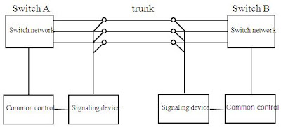
1.CAS (Channel Associated Signaling ):
Channel Associated Signaling is in-band signaling in which user call data and signaling are combined.
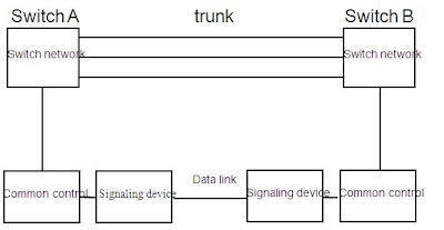
2.CCS (Common Channel Signaling ):
Common Channel Signaling is a signaling system used in telephone networks that separates signaling information from user data. Usually TS16 (Timeslot 16) on a E1 interface and TS1 (Timeslot 1) on a T1 interface, are exclusively designated to carry signaling relating to other traffic channels.
Channel Associated Signaling
Common Channel Signaling
1.2 signaling network
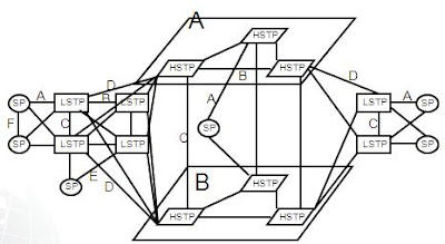
Signaling network
.No.7 signaling network is a specific network which is used to transfer the No.7 signaling
-It is composed of SP, STP and signaling link
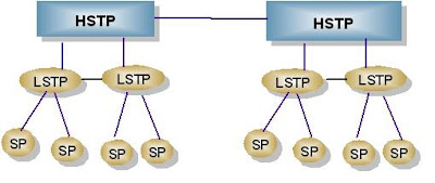
.Signaling network is a independent network form telephone network, in china the No7 signaling network has 3 layers
-HSTP
-LSTP
-SP
.Between two SP (SP or STP) there is a signaling link
-It is composed of SP, STP and signaling link
.Signaling network is a independent network form telephone network, in china the No7 signaling network has 3 layers
-HSTP
-LSTP
-SP
.Between two SP (SP or STP) there is a signaling link
The dual plane structure of signaling network
1.3 basic conception of signaling network
SP and STP
1.SP: SP is a node of signaling network to send or receive the signaling message, and is a initiation or destination of the signaling message
-OPC: it is a signaling point to generate the signaling message
-DPC: it is a signaling destination
-OPC: it is a signaling point to generate the signaling message
-DPC: it is a signaling destination
2.STP: if some signaling point is neither OPC nor DPC, it’s function is only to transfer the signaling message from one signaling link to another signaling link, this SP is STP
Signaling point
.24-bit signaling point combination
.14-bit signaling point combination
.14-bit signaling point combination
.Signaling link:
-signaling link is between 2 signaling points, and there are at most 16 signaling links between 2 signaling points which are connected to each other directly; If there more than 16 signaling links between 2 directly connected signaling points, the local or the peer end should add new signaling point
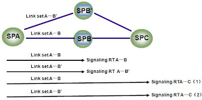
.Signaling link set:-signaling link is between 2 signaling points, and there are at most 16 signaling links between 2 signaling points which are connected to each other directly; If there more than 16 signaling links between 2 directly connected signaling points, the local or the peer end should add new signaling point
-Signaling link set is a group of signaling links which have same property, and these signaling links are between 2 adjacent signaling points
(SLC) Signaling link code and link number
.Link number is a number to distinguish the link in local office, it is unique in local office
Direct connection and similar direct connection
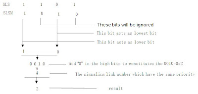
SLS and SLSM
.SLS: SLS has 4 bits (00~0F), is used to select signaling link for No.7
-SLS is circularly changed, in order to grantee the symmetrical burden of each link or link set
.SLSM:signaling link (link set) selection mask, it is indicated by a 4 bit codeSignaling link (set) selection setting principle
.Setting principle , suppose there are 4 link or link set:
Signaling route
.Signaling route is a logical conception which is used to indicate a path the signaling message go through from OPC to DPCChapter 2 basic conception of trunk network
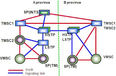
Trunk network
Office direction
.There is a office direction if there is direct trunk connection between 2 switch.Attention: G9 has office direction to the direct connected office, but just MSOFTX3000 has office direction, UMG8900 has no office direction
SRT and RT
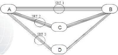
1.SRT -If there is a direct voice channel between two offices, it is taken that there is a sub-route between them
2.RT
-For an office direction, the set of all sub-routes to it is called a route, One route may contain multiple sub-routes, and different routes may contain the same sub-routes
2.RT
-For an office direction, the set of all sub-routes to it is called a route, One route may contain multiple sub-routes, and different routes may contain the same sub-routes
Trunk circuit and trunk group
.Trunk circuit:-The trunk circuit is the component constituting a trunk group, and one trunk circuit corresponds to one timeslot in E1 line
.Trunk group
-The trunk group is the component building a sub-route, and it is a set of trunk circuits with the same properties. It can be composed of one or multiple PCM systems.
-The trunk circuits to the same office direction are grouped into one trunk group
-The SS7 trunk group is generally bi-directional, and used to carry outgoing or incoming traffic.
CIC (Circuit Identification Code)
.The CIC is used to identify a circuit between two SPs. CIC fields only exist in the TUP and ISUP messages of circuit switched services. Because a CIC field is 12 bits long, there can be 4096 circuits between two SPs in maximum
CIC number principle
1. Office direction is the direct connection between 2 SPs. And only MSOFTX3000 but not UMG8900 has the conception of office direction.
2. The different between RT and SRT is that SRT is the direct voice channel between 2 offices and RT is the combination/group/set of SRTs for an office direction. In different RT may contains the same SRTs.
3. CIC is unique in the TUP and ISUP range!!!!! (NOT office direction?????). And there is 4096 configurable CIC (Circuit Identification Code) between 2 signaling points.
Chapter 3 SS7 basic protocol introduction
Corresponding Relations of
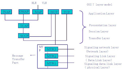
SS7 with OSI Seven-layer Architecture
MTP1、2、3 protocol
Signaling data link (MTP-1)
.It is equivalent to the physical layer of the OSI reference model and is used to generate and receive the signals through the physical channels. It defines the physical, electrical and functional characteristics of a signaling data link and the means to access it.
Signaling link functions (MTP-2)
.It is used to transfer signaling to a data link. The level 2 functions together with a level 1 signaling data link provide a signaling link for reliable signaling transfer between two directly associated signaling points; MTP2 can provide signal unit delimitation, signal unit alignment, error detection, error correction, initial alignment, processor outage, level 2 flow control and signaling link error monitoring
Signaling network functions (MTP-3)
.MTP3 implement the functions of the network layer of the OSI reference model, and is used to enable management message transmission between the signaling points for the purpose of ensuring a reliable transfer of the signaling messages over the signaling network in case that signaling links and signaling transfer points fail.
ISUP and TUP
1.ISUP (ISDN User Part ):-It defines the signaling messages, functions and procedures required to control voice and non-voice services (for example, circuit switched data communication). The ISUP can not only implement the functions of the Telephone User Part (TUP) and the Data User Part (DUP), but also achieve the ISDN services on a wide basis, thus having a spacious application scope
2.TUP (Telephone User Part )
-The TUP function is similar to ISUP, but can not support data type applications
SCCP protocol
.SCCP protocol (Signaling Connection Control Part ):-SCCP is one of the user parts in the hierarchical architecture of the Signaling System No. 7, and resident at the functional level 4.
-The SCCP provides additional functions to the Message Transfer Part (MTP) to cater for both connectionless as well as connection-oriented network services to transfer circuit related and non-circuit related signaling information and other types of information between exchanges and specialized centers in telecommunication networks through a SS7 network
MAP protocol
.MAP protocol (Mobile Application Part ):-MAP defines how information is exchanged between mobile system communication network entities for the purpose of achieving Mobile Station (MS) roaming function .
-MAP can support location update, authentication, encryption, hand over functions for MS
CAP protocol
.CAP (CAMEL Application Part ):-CAP is from INAP, and it is used for the IN services
-CAP enables signaling interworking between GSM Service Switching Function (gsmSSF), GSM Specialized Resource Function (gsmSRF) and GSM Service Control Function (gsmSCF) of radio IN functional entities, for the purpose of supporting CAMEL services
Chapter 4 mobility communication basic conception introduction
GSM area defination
WCDMA area defination
IMSI number
MCC:Mobile Country Code
MNC:Mobile Network Code
MSIN:Mobile Station Identification Number
NMSI:National Mobile Station Identity
IMSI number :
IMSI: International Mobile Subscriber Identity
IMSI number is a unique identifier allocated to each mobile subscriber in a GSM and UMTS network
It’s code type is E.212
IMSI can be saved in SIM card, HLR and VLR, and be transferred through MAP interface and wireless interface
IMSI has at most 15 digits(0-9), such as 456182300025256
TMSI numbe
TMSI number :
TMSI: Temporary Mobile Subscriber Identity
In order to ensure subscriber identity confidentiality the VLR (Visitor Location Register) and SGSN (Serving GPRS Support Node) may allocate TMSI to visiting mobile subscribers
IMEI number
TAC:Type Approval Code
FAC:Final Assembly Code
SNR:Serial Number
spare:standby bit
Example:490547403767335
MSISDN number
CC: Country Code, Cambodia country code is 855
NDC :National Destination Code
SN: Subscriber Number MSISDN number
MSISDN number :
-Mobile Station International ISDN Number
-The MSISDN Number is the standard international telephone number used to identify a given subscriber
-It’s code type is E.164
-MSISDN number can be saved in HLR and VLR, and can be transferred in MAP interface
Device number
MSC/VLR Number and HLR Number
MSC/VLR number :
-It’s code type is E.164
HLR number
-It’s code type is E.164
-It’s structure is CC+NDC+H0H1H2H3+0000
MSRN/HON
MSRN/HON number :
They are used to address the target MSC
They are generated by VLR temporary, when a MS act as a called party, or the MS is being in the handover procedure
LAI
.LAC:A Location Area is a number of cells (defined by the mobile operator) throughout which a GSM / UMTS mobile will be paged
.LAI: Location Area Identity
MCC:Mobile Country Code
MNC:Mobile Network Code
LAC: Location Area Code
MNC:Mobile Network Code
LAC: Location Area Code
SAI
.SA: Service area
-A Service Area consists of one or more cells within a given LA (Location Area) and may be used to assist in the delivery of location based services
.SAI: Service Area Identity
MNC:Mobile Network Code
LAC: Location Area Code
SAC: Service Area Code
CGI
.CGI: Cell Global Identity
MCC:Mobile Country Code
MNC:Mobile Network Code
LAC: Location Area Code
CI: Cell Identifier
Chapter 5 basic call flow introduction
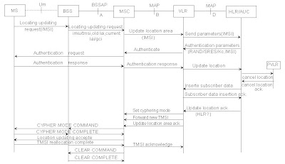
5.1 normal location update flow
Location update conception
Normal location update
5.2 call flow between 2 MSC
Call flow between MSCs
MS Call Another MS in same MSC


MS Call Another MS in same MSC









0 comments:
Post a Comment
If there is any comments,Please leave a comment at here.