Contents
Chapter1 Core Network Evolution
Definition of Core Network - CN includes a series of physical entities to realize user location management, network function and service control, such as (G)MSC, HLR, SCP, SMC,GSN etc.
- CN can be divided into three types: Home Network Domain, Transit Network Domain and Transit Network Domain. Ref. is 3GPP 23.101.
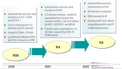
Release Evolution of WCDMA
Chapter2 R99 Core Network
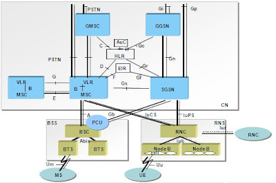
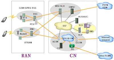
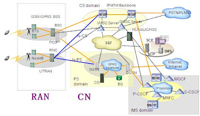
R99 Network Architecture
R99 Core Network-Features and Technologies
3.PS domain: used to provide Packet-switched service. Network mode is IP. Physical entities include SGSN, GGSN, CG , BG etc.
R99 Core network-Function Entity(1)
1.Function entity shared by CS domain and PS :-VLR: to deal with all kinds of data information of current mobile subscriber ;
-AUC: to store authentication information of mobile subscriber ;
-EIR: to store IMEI data of mobile subscriber;
-SMS: Short Message Center.
2. Function entity of CS domain:
-GMSC: to realize addressing function for different network.
-GMSC and MSC can be integrated together or separated independently.
-IWF: integrated together with MSC, to realize inter-working with PLMN and ISDN, PSTN , PDN (Mainly complete signaling transfer function), its functions can be defined based on specified services and network types.
3. Function entity of PS domain:
-SGSN: to realize packet switching function, signaling control function and route function of packet service.
-GGSN: to realize inter-working with PS domain and external data network.
-CG: to realize billing function of packet service.
-BG: to realize inter-working of two GPRS network and guarantee the security of network.
R99 Core Network-Interface(1)
1. Interface between CN and RAN/BSS:-A Interface: to realize mobile station management, base station management, mobility management and call processing, etc.
-Gb interface: to realize packet data transmit and mobility management.
-Iu-CS interface: to realize RNS management, mobility management and call control function.
-Iu-PS interface: its basic function is similar to Iu-CS interface.
2.CS internal interface:
-B interface (MSC-VLR): A private interface between VLR and MSC. It is used for the MSC to query the current location information of a Mobile Station (MS) from the Visit Location Register (VLR), or request the VLR to update the current location information of the MS or is used for the operations of supplementary services.
-C interface (MSC-HLR): to get MSRN, the IN service related subscriber status and location information.
-D interface (VLR-HLR): used to exchange the location information of the MS and the subscriber management information.
-E interface ( between MSC): to be used for handover process between two MSCs.
-F interface (MSC-EIR) : to be used for EIR to verify IMEI status information of mobile equipment.
-G interface (between VLR): to exchange IMSI and authentication information when MS moves from one VLR to another VLR.
3.PS internal interface:
-GS interface (SGSN-HLR): to exchange mobile location information and manage subscriber signed information. It is similar to C interface.
-Gn, Gp interface (SGSN-GGSN): GTP is adopted, used for establish tunnel and transmit data packet between GSN equipment.
-Gc interface (GGSN-HLR) : optional.
-Gf interface (SGSN-EIR) .
-Gi interface (GGSN – external network).
4. Common interfaces shared by CS and PS:
-Gs interface (MSC/VLR-SGSN): used for combined location update between MSC and SGSN) .
-H interface (HLR-AUC): used for authentication and ciphering. It is a private interface.
-Gs interface (MSC/VLR-SGSN): used for combined location update between MSC and SGSN) .
-H interface (HLR-AUC): used for authentication and ciphering. It is a private interface.
Chapter3 R4 Core Network
Section 1 Networking and Interface
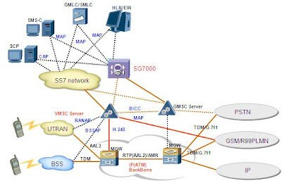
R4 Network Architecture
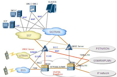
R4 Core Network-Function Entities
1.MSC Server: control layer, to realize MM (mobility management), CM ( call control), MGC (media gate control) .
2.MGW:bearer layer, to realize the exchange of voice and media flow, and provide all kinds sources, such as TC, EC, play announcement and receive DTMF.
3.SG: to realize signaling transfer from MTP (SS7 transmission layer) to SCTP/IP (SIGTRAN transmission layer).
R4 Core Network-Interface and Protocol (1)
1.Mc interface ((G)MSC Server–MGW) : H.248 is adopted, to realize the flexible connection processing for multi call mode, multi media;
2.Nc interface (MSC Server–(G)MSC Server) : to realize the inter-office call control. It adopts BICC protocol ;
3.Nb interface ( Between MGWs):to realize the transfer of control and user information (voice, data, picture, media) in bearer layer,and realize the transfer of different media frame format. RTP/UDP/IP and AAL2/ATM protocol is adopted.
Section 2 R4 Features

Section 2 R4 Features
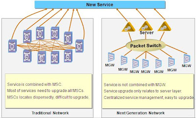
Bearer and Control Separated

Four-layer Architecture
Embedded SG-Save transmission link
Centralized Service Control
Distributed Architecture-Flexible networking
1.The advantage of distributed networking:
-Traffic route is the best, network performance is the best.
-Mostly suitable for the operators with wide coverage.
TFO and TrFO – Improve voice quality
1.The difference of TFO and TrFO:
-TFO set up the coder–free connection by in-band signal, while coder still need to work (used for monitor signal of TFO message) .
-TrFO set up the coder-free connection by out-band signal, but coder is not needed after connection is set up.
2.The advantage of TFO and TrFO:
+Improve voice quality:
-Voice coder has damaged compress for voice. It will reduce voice quality when coder is used.
-Can reduce the transmission delay.
+Save the power of equipment
-When TrFO is adopted, the coder function is bypassed, thus will save the power of equipment.
Chapter4 R5 Core Network
Section 1 R5 Networking
R5 Network Architecture
R5 Features
1.3GPP R5 Features:-Inherit all the WCDMA R4 service and functions.
-IMS ( IP Multimedia System) is added based on PS, CS of R5 is consistent with that of R4.
-Iu interface can select IP and ATM. IP based is a trend of networking.
-IP QoS is enhanced.
-Services are enhanced, such as OSA,Push Service
2.R5 realizes ALL IP network put forward by 3GPP.
-IP will become the bearing technology for all signaling message and change the original call flow.
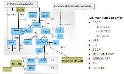
R5 Core Network-IMS (1)
R5 Core Network-IMS (2)
1.CSCF:Call Session Control Function-Is divided into P/S/I three types based on its function and location.
-P-CSCF(Proxy CSCF):It is the first connection point for subscriber in IMS and provide Proxy function. It can receive service request and transfer them, but can not modify the Request URI field in INVITE message; P-CSCF also can provide user agent function (UA), it can interrupt and independently produce SIP conversion at abnormal case.
-S-CSCF(Serving CSCF):S-CSCF is the core control of IMS, it is responsible for UE to register, authenticate and conservation control, realize conservation route function for calling and called IMS user. According to subscriber signed IMS triggered rule, it can trigger the value added service route to AS and control service negotiation.
-I-CSCF(Interrogating CSCF): similar as IMS gateway node, provide node distribution, route query and IMS Topology Hiding Inter-network function. R5 Core Network-IMS (3)
1.HSS:The Home Subscriber Server.
-HSS stores the IMS subscriber signed information, including basic identity, route information and service signed info. Centralized database, located at the top of IMS core network. It stores the following information:
-IMS subscriber identity (including public and private identity), number and address information.
-IMS subscriber security context: ciphering information for subscriber to access network for authentication, roaming restrict information.
-IMS subscriber route information: HSS supported route information, registration information and location information.
-IMS subscriber service signed information: including other AS value added service data.
Section 2 SIP
Introduction
SIP Development
1.SIP(Session Initiation Protocol):-It is application layer control protocol, used to setup, modify, and terminate multimedia session (including meeting). For example, internet telephone call.
.Originally derived from MBone experiment in 1996.
.In 1999, It was adopted as RFC2543 standard by IETF-MMUSIC work group.
.In 1999, SIP work group was established independently, later, two work group named as SIPPING and SIMPLE was newly set up, which is mainly devoted to SIP.
.In the July of 2002, it is turned to the new standard RFC3261.
.Most of the content was re-written. It is more clear and precise and some new features were added.
.Most of contents keep the backward compliance with RFC2543.
SIP Features
-Based on text code.
-Only concern about setup, modify and terminate the conservation. SIP-URL is uesd to indicate the resources or subscribers needed to be visited.
-Flexible extended and powerful negotiation mechanism: Supported, Unsupported, Require, ProxyRequire, Allow, Accept...
-Simple networking provides the flexibility, reliability and expandability. Relay equipment (Proxy and Redirecter) need not to care about the message content, just transfer transparently.
SIP Protocol Stack
SIP Application in IMS







0 comments:
Post a Comment
If there is any comments,Please leave a comment at here.