1.Definition and function:
Call Control Signaling like setting up a call, tear down, negotiation of parameters
Provides signaling independent of bearer technology and signal transport technology
BICC is Adaptation of ISUP as defined in the scope of Recommendation Q.1901 series
-BICC apply in the Nc interface
Basic Concept
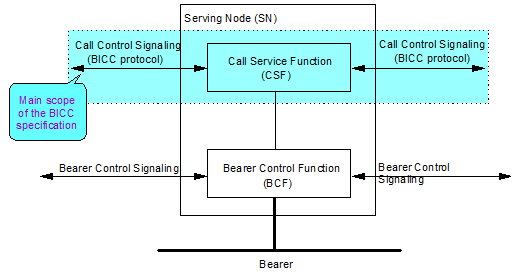
- Serving node:
CSF: Call Service Function, performs call control
BCF: Bearer Control Function, performs bearer control function
SN: CSF with associated BCF
CMN: CSF without any BCF associated
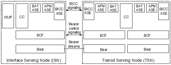
- SN types : The component of SN are :
1.ISN : provides the interface with non-BICC networks and terminal equipment
2.GSN : provides gateway functionality between two network domains
3.TSN : provides transit functionality between ISNs and GSNs
- Separation between call and bearer
Network model of BICC
BICC protocol Model
- Signalling Transport Layer :
MTP3 for TDM Network
SCTP over IP for IP network
SSLOP for TAM network
- STC : Signalling Transport Converters. Mapping function according to underlying layers
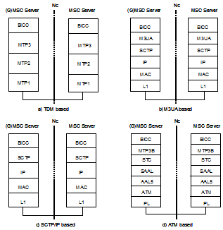
Structure of the Protocol Stack
there are 4 types of Protocol stacks :
1.TDM based
2. M3UA based
3.SCTP/IP based
4.ATM based
The 4 types of protoco stacks as above are depend each Telecom operators requirement, or the system support which type.
BICC Message Structure
- Call Instance Code (CIC) is a logic number associated with the inter-office calling relation
Format of BICC messages
- CIC
- is used to identify signalling relation between peer BICC entities and associate all the PDUs to that relation.
- message type code
- the mandatory fixed part
- the mandatory variable part
- the optional part, which may contain fixed length and variable length parameter fields
- All outgoing non test calls are blocked using those CIC values
- Incoming non test call with those CIC leads to error case
- Incoming Test calls with those CIC values are permitted to be carried out
- Outgoing test calls using those CIC values are also permitted
Main message of BICC protocol
- IAM:Initial address message
-APM:Application transport message
-ACM:Address complete message
-ANM:Answer message
-REL:Release
-RLC:Release complete
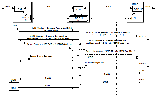
Basic Call Setup
- Forward Bearer Setup
No Tunnel case
Fast Tunnel
Delayed Forward Tunnel
- Backward Bearer Setup
No Tunnel Case
Delayed Backward Tunnel
Forward Bearer Setup
- Bearer setup is initiated in the forward direction of the call
- lCSF decides whether bearer setup will be in forward direction or in backward direction
- lCSF decides if tunnelling is supported. BCF decides if tunnelling is used
- lTunnelling is carrying Bearer Control Info embedded in BICC messages
Backward Establish Flow


0 comments:
Post a Comment
If there is any comments,Please leave a comment at here.